Welding Analysis and Weld Zone Preparation
A comprehensive guide to preparing weld samples for metallographic analysis, covering weld zone, heat-affected zone (HAZ), and fusion boundary preparation for different welding methods.
Table of Contents
Introduction
Welding creates complex microstructural zones that require specialized preparation techniques for accurate metallographic analysis. A typical weld contains multiple distinct regions: the weld metal (fusion zone), the heat-affected zone (HAZ), the fusion boundary, and the unaffected base metal. Each region has different microstructures and properties that must be properly revealed through careful sample preparation.
Proper preparation of weld samples is essential for:
- Evaluating weld quality and integrity
- Detecting defects (cracks, porosity, inclusions)
- Analyzing microstructural changes in the HAZ
- Verifying weld penetration and fusion
- Assessing post-weld heat treatment effectiveness
- Optimizing welding parameters
- Failure analysis of welded components
Key Challenge: Weld samples often contain multiple materials with different hardnesses and microstructures. This requires careful preparation to avoid relief, maintain edge retention, and reveal all zones clearly. The preparation must preserve the integrity of each zone while revealing their distinct microstructural features.
Understanding Weld Zone Regions
Before preparing weld samples, it's important to understand the different regions that will be examined. Each region has distinct characteristics and preparation requirements.
1. Weld Metal (Fusion Zone)
The weld metal is the region where the base metal and filler metal have melted and solidified. Characteristics include:
- As-cast microstructure: Columnar grains growing from the fusion boundary toward the weld centerline
- Dendritic structure: Often visible in welds, especially in aluminum and stainless steel
- Variable composition: May differ from base metal if filler metal is used
- Potential defects: Porosity, inclusions, cracks, incomplete fusion
2. Heat-Affected Zone (HAZ)
The HAZ is the region of base metal that was heated but not melted. It experiences microstructural changes due to the thermal cycle. The HAZ typically contains several sub-zones:
- Coarse-grained HAZ: Nearest to the weld, where grain growth occurred
- Fine-grained HAZ: Where recrystallization occurred
- Intercritical HAZ: Where partial transformation occurred (in steels)
- Subcritical HAZ: Where only tempering or aging occurred
The HAZ is often the most critical region for weld performance, as it can be the weakest link in the weldment.
3. Fusion Boundary
The fusion boundary is the interface between the weld metal and the HAZ. This region is critical for analysis because:
- It marks the transition from melted to unmelted material
- It may contain defects such as lack of fusion
- It shows the extent of weld penetration
- It reveals the quality of the weld fusion
4. Base Metal
The unaffected base metal provides a reference microstructure for comparison. It should show the original material structure without thermal effects from welding.
Preparation Goal: The ideal weld sample preparation reveals all zones clearly with sharp boundaries, no relief between zones, and microstructures that accurately represent each region. This requires careful attention to grinding, polishing, and etching techniques.
Sectioning Weld Samples
Proper sectioning is critical for weld analysis. The section location and orientation determine what can be observed and analyzed.
Section Orientation
Choose section orientation based on what you need to analyze:
- Transverse section: Perpendicular to the weld direction - shows the full cross-section including all zones. Most common for general analysis.
- Longitudinal section: Parallel to the weld direction - shows weld bead shape, penetration profile, and defects along the weld length.
- Oblique section: At an angle - useful for examining specific features or defects.
Section Location
Select section locations that provide the most information:
- Weld centerline: Shows the full weld cross-section
- Weld toe: Critical area where stress concentrations occur
- Weld root: Important for penetration analysis
- Defect locations: If defects are suspected, section through them
Sectioning Techniques
Use appropriate sectioning methods to minimize damage:
- Abrasive cutoff: Use a wheel speed of roughly 2,500-4,500 surface feet per minute (SFM) with a gentle feed rate and copious coolant to prevent overheating
- Coolant: Essential to prevent thermal damage to the HAZ microstructure
- Multiple cuts: For large samples, make multiple cuts to isolate the region of interest
- Preserve features: Leave adequate material around features of interest
Warning: Overheating during sectioning can alter the HAZ microstructure, making it impossible to accurately assess the weld. Always use adequate coolant and appropriate cutting speeds.
Sample Size
Weld samples should be large enough to include:
- Complete weld metal cross-section
- Full HAZ on both sides (for butt welds)
- Adequate base metal for reference
- Typically 25-32 mm width is sufficient for most analyses
Sectioning Equipment for Weld Samples
Proper sectioning equipment is essential for preparing weld samples without damaging the HAZ microstructure:
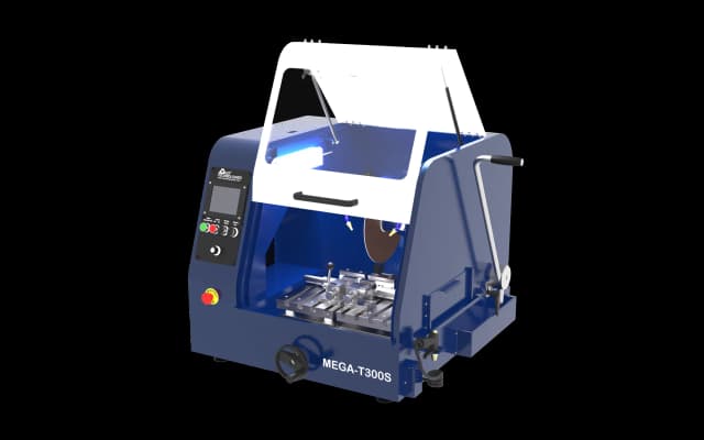
Abrasive Cutoff Machines
Precision cutoff machines with variable speed control and adequate coolant systems are essential for sectioning welds without thermal damage.
View Cutoff Machines →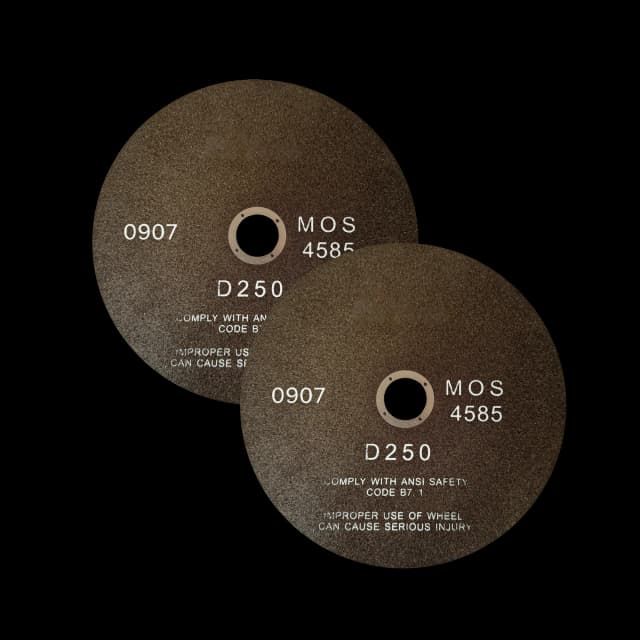
Cutting Wheels
Appropriate abrasive cutting wheels designed for the material being sectioned help minimize damage and ensure clean cuts.
View Cutting Wheels →Mounting Considerations
Mounting weld samples provides several advantages and requires specific considerations due to the multiple zones with different properties.
Why Mount Weld Samples
- Edge retention: Critical for examining weld boundaries and HAZ
- Easier handling: Weld samples are often irregularly shaped
- Protection: Prevents damage to delicate weld features
- Orientation: Ensures proper orientation for analysis
Mounting Material Selection
The canonical mount for weld cross-section analysis is glass-filled epoxy compression mount. Plain phenolic (Bakelite-style) is the wrong choice for serious weld work — it wears 2-3× faster than the steel during long polishes and rounds the sample-mount boundary by 10-50 µm. Worse, the HAZ in welded structural steels typically contains martensite or bainite that is much harder than the base metal, so phenolic differential-wears against the hard HAZ regions and against the fusion boundary itself, biasing both HAZ-width measurements and hardness-traverse profiles. Glass-filled epoxy is what makes those measurements defensible.
- Glass-filled epoxy (preferred for weld analysis): Best edge retention; matches the differential-wear profile of welded steel and stainless. The right answer for fusion-boundary characterization, HAZ-width measurement, hardness-traverse work, and any case where the analysis turns on near-fusion-boundary features.
- Plain epoxy: Acceptable for low-stakes general-structure work where edge retention isn't critical. Cures at standard compression-mounting temperatures (about 150-180°C).
- Phenolic resins: Acceptable only for soft non-ferrous welds (Al, Cu) where the differential-wear pattern is reversed; not appropriate for steel/stainless welds where edge retention matters.
- Conductive mounting (carbon- or Cu-filled): For SEM/EBSD electrical continuity, not for mechanical edge retention. If you need both, use glass-filled conductive epoxy.
Mounting Orientation
Mount samples to optimize analysis:
- Weld perpendicular to mount surface: Most common orientation - allows examination of all zones in cross-section
- Mark weld location: Mark the weld centerline or other features before mounting to maintain orientation
- Multiple samples: Can mount multiple weld sections in one mount for comparison
Special Considerations
- Porosity preservation: Use vacuum mounting if porosity analysis is needed
- Edge protection: Consider using edge protection techniques for delicate weld boundaries
- Mount size: Standard 25-32 mm diameter works well for most analyses
Mounting Equipment and Materials
Proper mounting equipment and materials are essential for preserving weld zone boundaries and maintaining edge retention:
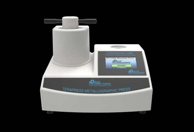
Compression Mounting Presses
Compression mounting presses provide consistent pressure and temperature control for mounting weld samples with phenolic or epoxy resins.
View Mounting Presses →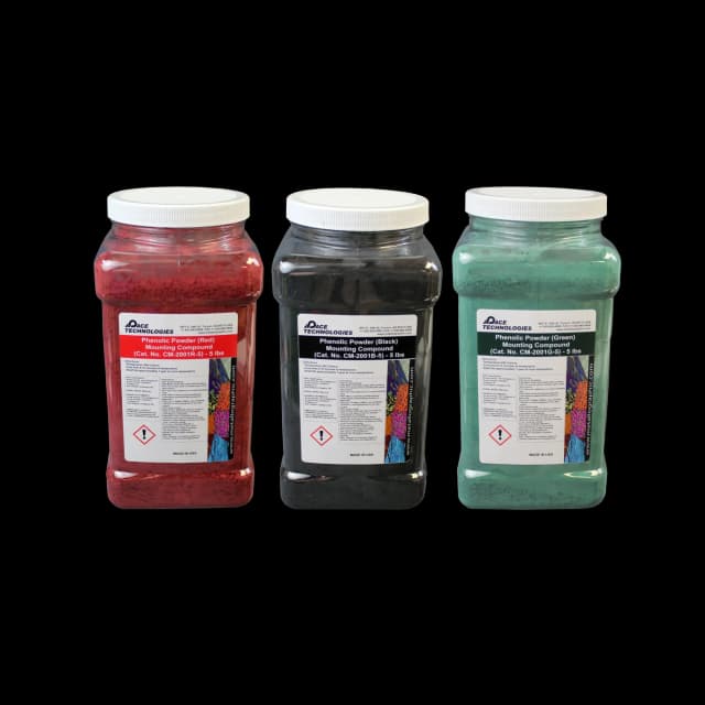
Mounting Materials
Compression mounting resins range from phenolic for routine work to glass-filled epoxy, which provides the best edge retention for weld zone boundary analysis.
View Mounting Materials →Grinding and Polishing Weld Samples
Weld samples present unique challenges during grinding and polishing due to the different hardnesses and microstructures in each zone. Careful technique is required to avoid relief and maintain zone boundaries.
Grinding Sequence
Use a progressive grinding sequence to remove sectioning damage:
- 120 grit: Remove sectioning damage (60-90 seconds)
- 240 grit: Remove previous scratches (60-90 seconds)
- 400 grit: Further refinement (60-90 seconds)
- 600 grit: Final grinding step (60-90 seconds)
Grinding Techniques for Welds
- Rotate 90°: Rotate sample 90° between each grit to ensure complete scratch removal
- Moderate pressure: Use consistent, moderate pressure - avoid excessive pressure that could cause relief
- Check zone boundaries: Periodically check that zone boundaries remain visible and sharp
- Adequate time: Spend sufficient time at each step to remove all previous scratches
- Water lubrication: Use water as lubricant to prevent overheating
Polishing Sequence
Use a progressive polishing sequence:
- 9 μm diamond: 3-5 minutes on a hard woven cloth
- 3 μm diamond: 3-5 minutes on medium-hard cloth
- 1 μm diamond: 2-3 minutes on soft cloth
- 0.05 μm colloidal silica: 1-2 minutes on soft cloth (optional, for high-quality finish)
Avoiding Relief
Relief (uneven polishing between zones) is a common problem with weld samples. To minimize relief:
- Use appropriate cloths: Harder cloths for harder zones, but avoid too much variation
- Moderate pressure: Avoid excessive pressure that can cause differential removal
- Shorter polishing times: Don't over-polish - stop when scratches are removed
- Check frequently: Examine under microscope to detect relief early
- Final polish: Use colloidal silica for final polish to minimize relief
Tip: If relief becomes a problem, return to a coarser polishing step and use lighter pressure and shorter times. Relief is easier to prevent than to fix.
Grinding and Polishing Equipment
Proper grinding and polishing equipment is essential for preparing weld samples without creating relief between zones:
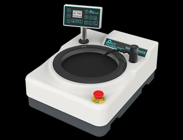
Grinder Polishers
Manual grinder polishers with variable speed control allow precise control over grinding and polishing pressure, essential for avoiding relief in weld samples.
View Grinder Polishers →
Polishing Cloths
Appropriate polishing cloths (hard for initial polishing, soft for final polishing) help minimize relief between weld zones with different hardnesses.
View Polishing Cloths →Edge Retention
Maintaining sharp zone boundaries is critical for weld analysis:
- Glass-filled epoxy mount: The single most consequential edge-retention decision; see the Mounting section above.
- Lighter pressure: Use lighter pressure near boundaries
- Shorter times: Cap final polish at 90 s + flush — over-polishing on soft napped pads rounds the boundary even on a glass-filled epoxy mount
- Harder final-step pad: Synthetic suede instead of chemotextile for the final step preserves the fusion boundary better
- Final check: Verify boundaries are sharp before etching
Etching Techniques for Welds
Etching is critical for revealing weld microstructures. Different zones may require different etchants or etching times. The goal is to reveal all zones clearly with good contrast.
Macroetching First — ASTM E340
Before any microetching work, weld cross-sections are typically inspected at low magnification using a macroetch per ASTM E340 (or ASTM E381 for steel-product macroetch acceptance). The macroetch reveals the gross weld geometry — fusion zone outline, HAZ extent, weld penetration depth, root condition, multipass boundaries — at 1-10× magnification, before any decisions are made about whether the weld is worth detailed microstructural analysis. For carbon-steel welds, a typical macroetch is 50% HCl (50 mL HCl + 50 mL H₂O) heated to 70-80 °C for several minutes, or 10% ammonium persulfate at room temperature. For stainless weld macroetch, glyceregia (10 mL HNO₃ + 20 mL HCl + 30 mL glycerol) by swab or immersion. Macroetching catches gross defects (lack of fusion, root cracks, weld undercut, multipass inter-run defects) that microscopic examination won't catch on a single field of view.
Microetching by Alloy Class
After macroetch, microetching reveals the microstructure within each zone. The right etchant depends on the base metal class — pick by the table below rather than reaching for a single "general purpose" reagent.
Carbon and Low-Alloy Steel Welds
- 2% Nital (2 mL HNO₃ in 98 mL ethanol): The default first-pass etch — reveals ferrite, pearlite, and martensite across all three regions (fusion zone, HAZ, base metal). Swab 5-15 s.
- 2% Nital then 4% Picral (sequential): When pearlite washes out under Nital alone, follow with a second swab of 4% Picral. Picral darkens cementite and sharpens pearlite — particularly valuable for hardened HAZ regions in 4140-class welds.
- Beraha's tint etch (canonical for ferritic HAZ characterization): Beraha I (10 mL HCl + 90 mL H₂O + 1 g K₂S₂O₅) by immersion 30-180 s. Plain Nital cannot separate ferrite, pearlite, bainite, and martensite cleanly across the HAZ subzones (coarse-grained, fine-grained, intercritical, subcritical). Beraha tints each phase a distinct color, which is what the handbook recommends for serious HAZ characterization on ferritic-base welds.
- Picric must stay wetted: Picral and Vilella's both contain picric acid. Store stock wetted at all times — dry picric is friction- and shock-sensitive (effectively a primary explosive).
Austenitic Stainless Steel Welds (304, 316, 321, 347)
- Glyceregia (10 mL HNO₃ + 20 mL HCl + 30 mL glycerol): The canonical chemical etch for austenitic stainless. Immerse 10-60 s. Mix fresh; activity decays within an hour.
- 10% Oxalic acid, electrolytic (10 g oxalic in 100 mL H₂O at 6 V, 30-60 s): Cleaner grain boundaries than Glyceregia, no flash etching. The preferred technique for HAZ and base-metal characterization on austenitic welds. At 6 V for 90 s, this is also ASTM A262 Practice A for sensitization detection — directly relevant to QC of welded austenitic stainless that will see hot-water or chloride service.
- Lichtenberger-Bloech color etch (canonical for solidification structure): Color tint that reveals dendrite and cell structure in the austenitic weld metal — the structural feature that distinguishes a high-quality fully-mixed weld from a fast-frozen as-cast structure with potential hot-cracking susceptibility. Pair with 10% oxalic for HAZ to get the full weld characterization.
Note: Vilella's reagent (1 g picric + 5 mL HCl + 95 mL ethanol) is sometimes listed for austenitic stainless welds, but its canonical use is martensitic and ferritic stainless, not austenitic. Use Glyceregia or oxalic electrolytic for austenitic; reserve Vilella's for martensitic / ferritic / PH stainless welds.
Duplex Stainless Steel Welds (2205, 2507)
- Beraha's I (10 mL HCl + 90 mL H₂O + 1 g K₂S₂O₅): Immerse 30-180 s. Tints ferrite blue/brown, leaves austenite white. Reveals the ferrite-austenite distribution differently in fusion zone vs. base metal — the canonical etch for verifying that the duplex weld metal has the target 30-70% austenite fraction (per ASTM A923). The fusion zone in a duplex weld is typically more ferritic than the base metal because of fast cooling; Beraha shows this directly.
- Klemm's I (50 mL stock saturated Na₂S₂O₃ + 1 g K₂S₂O₅): Even more vivid color contrast than Beraha I. Surface must be deformation-free for Klemm to develop properly.
Martensitic and Ferritic Stainless Steel Welds (410, 420, 430, 446)
- Vilella's reagent (1 g picric + 5 mL HCl + 95 mL ethanol): Swab 5-60 s. Reveals martensite, ferrite, and prior-austenite grain boundaries.
- 4% Picral: Alternative for martensitic-stainless HAZ when Vilella's under-attacks.
Precipitation-Hardening Stainless Welds (17-4 PH, 15-5 PH)
- Marble's Reagent (4 g CuSO₄ + 20 mL HCl + 20 mL H₂O): Swab 10-60 s. The handbook-canonical etch for PH stainless and Ni-base alloys.
Aluminum Welds
- Keller's reagent (2 mL HF + 3 mL HCl + 5 mL HNO₃ + 190 mL H₂O): Swab 5-30 s. The standard etch for aluminum welds; reveals grain boundaries and second phases. HF safety: fume hood, HF-rated PPE, calcium gluconate gel on hand. Never let the surface dry between application and rinse — HF residues continue to attack until flushed.
- Barker's anodizing (5 mL HBF₄ in 200 mL H₂O at 20 V, 60-120 s): Electrolytic anodizing technique for grain orientation contrast under polarized light. Particularly useful for grain-size measurement in the weld metal where each grain shows a distinct color. Note this is anodic, not chemical — requires a low-voltage power supply.
- Polarized light examination: Often reveals dendritic structure in weld metal without etching.
Etching Strategy
When etching weld samples:
- Start light: Begin with shorter etching times - you can always etch more
- Check frequently: Examine under microscope to assess etching progress
- Zone-specific: Different zones may etch at different rates - adjust accordingly
- Multiple etches: Sometimes multiple etchants are needed to reveal all features
- Document: Record etchant and etching time for reproducibility
Etching Tip: If one zone is over-etched while another is under-etched, try using a gentler etchant or shorter time, then selectively re-etch specific zones if needed. Sometimes a compromise is necessary to reveal all zones adequately.
Etching Equipment and Reagents
Proper etching equipment and reagents are essential for revealing weld zone microstructures:
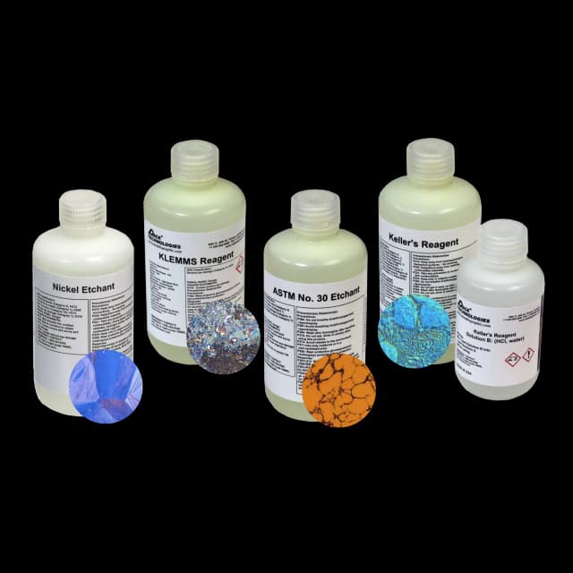
Etching Reagents
Standard etchants for weld microstructure: Nital and Beraha for ferrous welds, Glyceregia / 10% oxalic / Lichtenberger-Bloech for austenitic stainless welds, Beraha I / Klemm I for duplex welds, Vilella's for martensitic / ferritic stainless welds, Keller's for aluminum welds.
View Etchants →
Metallurgical Microscopes
High-quality metallurgical microscopes with reflected light capabilities are essential for examining weld zones, HAZ, and fusion boundaries at appropriate magnifications.
View Microscopes →Welding Methods and Their Characteristics
Different welding methods produce different microstructures and require specific preparation considerations. Understanding the welding method helps guide preparation and analysis.
TIG (Tungsten Inert Gas) Welding
TIG welding produces high-quality welds with good control. Characteristics:
- Narrow HAZ: Concentrated heat input creates a narrow HAZ
- Fine microstructure: Typically produces fine-grained weld metal
- Good fusion: Usually excellent fusion with base metal
- Preparation: Standard preparation techniques work well
- Analysis focus: Weld metal quality, HAZ width, fusion boundary
MIG (Metal Inert Gas) / MAG (Metal Active Gas) Welding
MIG/MAG welding is common in production. Characteristics:
- Wider HAZ: Higher heat input creates a wider HAZ
- Layered structure: Multiple passes create layered microstructure
- Potential defects: May have porosity or incomplete fusion between passes
- Preparation: May need to examine multiple layers
- Analysis focus: Inter-pass regions, HAZ extent, overall weld quality
Friction Stir Welding (FSW)
FSW is a solid-state joining process. Characteristics:
- No melting: Material doesn't melt, so no traditional fusion zone
- Stir zone: Region where material was plastically deformed and mixed
- Thermo-mechanically affected zone (TMAZ): Unique to FSW
- Fine grains: Often produces very fine-grained structures
- Preparation: Standard techniques, but focus on stir zone and TMAZ
- Analysis focus: Stir zone microstructure, TMAZ characteristics, material flow patterns
Electron Beam Welding (EBW)
EBW produces deep, narrow welds. Characteristics:
- Very narrow HAZ: Concentrated energy creates extremely narrow HAZ
- Deep penetration: Can create very deep welds
- Keyhole formation: May have keyhole-related features
- Preparation: Standard techniques, but HAZ may be difficult to resolve
- Analysis focus: Weld depth, HAZ width, keyhole features
Resistance Welding (Spot, Seam)
Resistance welding creates localized welds. Characteristics:
- Small weld nugget: Weld is typically small and localized
- Narrow HAZ: Heat is very localized
- Preparation: Section through the nugget center
- Analysis focus: Nugget size, fusion, HAZ extent
Dissimilar Metal Welds
Dissimilar welds (carbon steel ↔ stainless, stainless ↔ Ni-base, Al ↔ steel via transition joints) are common in process industries — boiler-tube transitions, bimetallic pressure vessels, automotive multi-material structures. They require a two-step etching strategy because one etchant rarely reveals both alloy classes equally:
- Step 1: Etch one base metal with its canonical etchant (e.g., 2% Nital for the carbon-steel side). Document the carbon-steel structure photographically before proceeding.
- Step 2: Mask the etched side with lacquer or PTFE tape, then etch the other base with its canonical etchant (e.g., Glyceregia or 10% oxalic for the austenitic stainless side, or Marble's for a Ni-base side).
- Fusion zone interpretation: The fusion zone in a dissimilar weld is typically a graded composition (the "dilution zone") with mixed structure, and may etch differently from either base. Document the gradient — it carries the dilution information that drives weld quality assessment.
- Common pitfall: Etching with one alloy class's reagent for long enough to reveal the other class's structure typically over-etches the first class. The two-step approach is non-optional for serious dissimilar-weld characterization.
In-Service Inspection — Field Replicas (ASTM E1351)
For welds in operating equipment that cannot be sectioned — pressure vessels, pipelines, large structural welds, irreplaceable components — destructive metallography isn't possible. The non-destructive alternative is the field metallographic replicatechnique per ASTM E1351 (Standard Practice for Production and Evaluation of Field Metallographic Replicas):
- Surface preparation in-situ: Hand-grind and polish a 25-50 mm patch on the component surface using portable grinder/polisher and progressively finer abrasives. Etch the patch with the appropriate reagent for the alloy class (Nital for carbon steel, Glyceregia for stainless, etc.).
- Replica application: Apply a softened cellulose-acetate film or silicone replicating compound to the etched surface. The replica picks up the topographic relief produced by etching.
- Lift, mount, examine: Lift the cured replica, mount it on a glass slide (acetate) or in epoxy (silicone), and examine under reflected-light microscopy. The image is a faithful negative of the etched component surface.
- Common applications: Creep-damage assessment in high-temperature steam piping (Type IV cracking, cavitation), in-service inspection of austenitic stainless welds on AISI 304 components, fatigue-crack monitoring at known stress concentrators on aerospace structures.
- Limits: Replicas resolve features down to ~1 µm; finer features (sub-grain structure, precipitates < 1 µm) require destructive sampling. Surface prep quality on the component is the primary limit on image quality — field surface prep is harder than lab surface prep, and the replica only shows what was on the surface when it was applied.
Preparation Note: Regardless of welding method, the fundamental preparation principles remain the same: proper sectioning, mounting, grinding, polishing, and etching. The differences lie in what you're looking for and how the zones appear after preparation.
Defect Detection in Welds
One of the primary purposes of weld metallography is detecting defects that could compromise weld integrity. Proper preparation is essential for accurate defect identification.
Common Weld Defects
Porosity
- Appearance: Round or irregular voids in the weld metal
- Preparation: Use vacuum mounting to preserve porosity. Avoid over-polishing which can round or close pores.
- Analysis: Measure size, distribution, and location
Cracks
- Types: Hot cracks, cold cracks, stress corrosion cracks
- Preparation: Section through cracks. Use careful polishing to avoid smearing or closing cracks.
- Analysis: Identify crack type, location, propagation path, and cause
Incomplete Fusion
- Appearance: Lack of fusion between weld passes or between weld and base metal
- Preparation: Section to show fusion boundaries clearly. Proper etching reveals lack of fusion.
- Analysis: Assess extent and location of incomplete fusion
Inclusions
- Types: Slag inclusions, oxide inclusions, tungsten inclusions (in TIG)
- Preparation: Standard preparation, but avoid over-polishing which can pull out inclusions
- Analysis: Identify type, size, and distribution
Undercut
- Appearance: Groove at weld toe where base metal was melted away
- Preparation: Section through weld toe. Maintain edge retention to show undercut clearly.
- Analysis: Measure depth and assess severity
Preparation for Defect Analysis
- Section location: Section through suspected defects
- Preserve defects: Use techniques that preserve defect morphology
- Avoid artifacts: Distinguish real defects from preparation artifacts
- Multiple sections: Sometimes multiple sections are needed to fully characterize defects
- Documentation: Document defect location, size, and characteristics
Important: Be careful to distinguish real defects from preparation artifacts. Pullouts, smearing, and contamination can look like defects. Experience and careful preparation help avoid misidentification.
Microstructure Analysis of Weld Zones
Each weld zone has characteristic microstructures that provide information about weld quality, properties, and potential issues. Understanding what to look for in each zone guides effective analysis.
Weld Metal Microstructure
The weld metal microstructure depends on composition, cooling rate, and welding parameters:
- Columnar grains: Growing from fusion boundary toward centerline
- Dendritic structure: Visible in many welds, especially aluminum and stainless steel
- Second phases: Precipitates, inclusions, or intermetallics
- Grain size: Can vary across the weld
- Defects: Porosity, cracks, inclusions
HAZ Microstructure
The HAZ microstructure reveals the thermal history:
- Grain growth: Coarse grains in the high-temperature region
- Phase transformations: In steels, may show martensite, bainite, or other transformation products
- Precipitation: May show over-aging or dissolution of precipitates
- Recrystallization: Fine grains in recrystallized regions
- Softening: In age-hardened alloys, may show softening
HAZ heterogeneity is data, not a defect. A sharp transition in microstructure across the weld line — with the HAZ looking distinctly different from both the fusion zone and the unaffected base metal — is exactly what a properly-developed etch should reveal. Beginners sometimes mistake clean HAZ revelation for a heterogeneous-etch artifact and try to "fix" it by re-etching uniformly, which destroys the HAZ contrast. If the etch is showing two or three distinct zones cleanly across the fusion boundary, the etch is working correctly — proceed to characterization. The only case where uniform etch behavior across the weld line is correct is on a fully post-weld-heat-treated component where the HAZ has been deliberately homogenized.
Fusion Boundary
The fusion boundary should show:
- Sharp transition: Clear boundary between weld and base metal
- Good fusion: No gaps or lack of fusion
- Grain growth: Grains growing from base metal into weld
- No defects: No cracks or other defects at the boundary
Analysis Magnifications
Use appropriate magnifications for different analyses:
- Low (50-100x): Overall weld structure, zone identification, defect location
- Medium (200-500x): Detailed microstructure, grain structure, phase identification
- High (500-1000x): Fine details, precipitates, small defects
Weld Microstructure Examples
Understanding typical weld microstructures helps in analysis and interpretation. When examining weld samples, look for:
Stainless Steel Welds
- • Distinct weld metal with columnar grains
- • HAZ showing grain growth and phase changes
- • Delta ferrite in austenitic welds
- • Fusion boundary clearly visible
Austenitic: Glyceregia or 10% oxalic electrolytic, with Lichtenberger-Bloech for solidification. Duplex: Beraha I or Klemm I tint. Martensitic / ferritic: Vilella's.
Carbon Steel Welds
- • Weld metal with as-cast microstructure
- • HAZ showing grain growth and transformation
- • Possible martensite or bainite in HAZ
- • Base metal with original structure
Etched with 2% Nital or 4% Picral
Aluminum Welds
- • Dendritic structure in weld metal
- • Recrystallized grains in HAZ
- • Precipitate distribution changes
- • Possible softening in HAZ
Etched with Keller's reagent (HF safety) or anodized with Barker's reagent for grain orientation under polarized light
Friction Stir Welds
- • Stir zone with fine recrystallized grains
- • TMAZ showing deformation structure
- • Material flow patterns
- • No traditional fusion zone
Material-specific etchants required
Note: Actual microstructures will vary based on welding method, material composition, process parameters, and heat treatment. Always compare observed microstructures with expected structures for the specific material and welding process. Document all observations with photographs at appropriate magnifications.
Documentation
Document your analysis with:
- Photographs: At appropriate magnifications showing all zones
- Measurements: Zone widths, grain sizes, defect sizes
- Descriptions: Microstructural features observed
- Comparisons: Compare with specifications or standards
Standards and References for Weld Analysis
Standards directly relevant to weld preparation, macroetching, microetching, in-service inspection, and acceptance criteria:
Macroetching and Acceptance
- ASTM E340 — Standard Practice for Macroetching Metals and Alloys. The canonical macroetch reference; covers reagent selection, etching procedures, and zone delineation for weld cross-sections.
- ASTM E381 — Standard Method of Macroetch Testing Steel Bars, Billets, Blooms, and Forgings. Acceptance criteria for steel-product macroetch (segregation, porosity, flow lines) — frequently extended to weld inspection on steel components.
Microetching and Etchant Reference
- ASTM E407 — Standard Practice for Microetching Metals and Alloys. Numeric IDs for standard etchants (Nital, Picral, Vilella's, Glyceregia, Marble's, Keller's, Kroll's, etc.) — the reference cited when a weld procedure specifies an etchant by ASTM E407 number.
Phase-Specific QC and Defect Detection
- ASTM A262 — Detecting Susceptibility to Intergranular Attack in Austenitic Stainless Steels. Practice A oxalic electrolytic — the canonical sensitization detection for welded austenitic stainless that will see corrosive service.
- ASTM A923 — Detecting Detrimental Intermetallic Phase in Duplex Austenitic/Ferritic Stainless Steels. The sigma/chi phase QC standard for welded 2205, 2507, and similar duplex grades — directly relevant to verifying the 30-70% austenite fraction in duplex weld metal.
In-Service / Non-Destructive
- ASTM E1351 — Standard Practice for Production and Evaluation of Field Metallographic Replicas. Cellulose-acetate or silicone replication of in-service component surfaces for non-destructive metallographic examination — the standard route for welds in operating equipment that cannot be sectioned.
Mechanical Testing References
- AWS B4.0 — Standard Methods for Mechanical Testing of Welds. Broader scope than metallography, but references metallographic methods for weld qualification and procedure verification.
For a comprehensive ASTM standards reference, see the ASTM Standards Reference.
Best Practices for Weld Analysis
Following best practices ensures reliable, reproducible weld analysis results.
Preparation Best Practices
- Plan ahead: Determine what you need to analyze before sectioning
- Proper sectioning: Use appropriate speeds and coolant to prevent damage
- Consistent technique: Follow standardized procedures for reproducibility
- Check progress: Examine samples at each preparation step
- Avoid relief: Use appropriate techniques to minimize relief
- Proper etching: Use correct etchants and times for the material
Analysis Best Practices
- Systematic examination: Examine all zones systematically
- Multiple magnifications: Use different magnifications for different purposes
- Document everything: Record all observations and measurements
- Compare zones: Compare weld zones with base metal
- Reference standards: Use applicable standards for evaluation
- Expert consultation: Consult experts when needed
Quality Control
- Standard procedures: Follow documented procedures consistently
- Calibration: Ensure equipment is properly calibrated
- Reference samples: Use reference samples to verify procedures
- Training: Ensure operators are properly trained
- Review: Have results reviewed by qualified personnel
Common Mistakes to Avoid
- Overheating during sectioning: Can alter HAZ microstructure
- Excessive relief: Makes zone boundaries unclear
- Over-etching: Can obscure microstructural details
- Poor edge retention: Makes boundary analysis difficult
- Inadequate documentation: Makes results difficult to reproduce or verify
- Misidentifying artifacts: Confusing preparation artifacts with real features
Remember: Good weld analysis requires patience and attention to detail. Take time at each step to ensure proper preparation. The quality of your analysis depends directly on the quality of your preparation.
Essential Equipment for Weld Analysis
To perform comprehensive weld analysis, you'll need proper equipment for sample preparation and examination. Here are the key tools:
Abrasive Cutoff Machines
Precision cutoff machines with variable speed control and adequate coolant systems are essential for sectioning welds without thermal damage to the HAZ.
View Cutoff Machines →Compression Mounting Presses
Mounting presses provide consistent pressure and temperature control for mounting weld samples with phenolic or epoxy resins, essential for edge retention.
View Mounting Presses →Grinder Polishers
Manual grinder polishers with variable speed control allow precise control over grinding and polishing pressure, essential for avoiding relief in weld samples.
View Grinder Polishers →Metallurgical Microscopes
High-quality metallurgical microscopes with reflected light capabilities are essential for examining weld zones, HAZ, and fusion boundaries at appropriate magnifications.
View Microscopes →Ready to Analyze Your Welds?
Now that you understand weld zone preparation, explore our material-specific guides or learn more about related techniques.