Cast Iron Sample Preparation
A comprehensive guide to preparing cast iron samples for metallographic analysis, with special emphasis on preserving graphite structure and revealing matrix microstructure.
Introduction
Cast iron preparation presents unique challenges that distinguish it from steel preparation. The defining characteristic of cast iron is its graphite structure, which must be preserved throughout the entire preparation process. Unlike steel, where the microstructure is revealed primarily through etching, cast iron's graphite is revealed by proper polishing — etching reveals the matrix structure (ferrite, pearlite, or bainite).
Examine unetched first. The canonical cast iron workflow per ASTM A247(graphite microstructure rating; ISO 945 is the international equivalent) is to assess graphite morphology — flake, nodular, vermicular, temper carbon — on the as-polished surface beforeany etching. Etching attacks the matrix and distorts apparent graphite shape, so post-etch nodularity counts on ductile iron per ASTM A247 are unreliable. Document the unetched view first; etch second.
Critical Principle: Graphite preservation is the most important aspect of cast iron preparation. Graphite is soft and can be easily removed or damaged during grinding and polishing. Gentle techniques and careful monitoring are essential.

Nodular cast iron, 200X magnification. This image shows the characteristic spheroidal graphite structure and matrix. Proper preparation preserves graphite while revealing matrix microstructure through etching.
Cast iron types vary significantly in their graphite morphology and matrix structure:
- Gray Cast Iron (ASTM A48): Flake graphite in pearlite or ferrite matrix (163-187 HB)
- Ductile Cast Iron (ASTM A536): Spheroidal (nodular) graphite in pearlite or ferrite matrix (217 HB) — nodularity rated per ASTM A247
- Malleable Cast Iron (ASTM A220): Temper carbon nodules in ferrite or pearlite matrix (163 HB)
- Austempered Ductile Iron (ADI): Spheroidal graphite in ausferrite matrix — acicular (needle-like) ferrite + carbon-enriched retained austenite. Ausferrite resembles bainite under the microscope but contains no carbides (310 HB, very hard)
- Compacted Graphite Iron (CGI): Vermicular (compacted) graphite in pearlite matrix (230 HB) — graphite shape is between gray and ductile
- White Cast Iron / Ni-Hard / High-Cr Iron: Carbide-rich, abrasion-resistant cast iron with no free graphite. Diamond grinding ladder required — chromium carbides cannot be cleanly cut by SiC abrasive, the same SiC-vs-carbide issue that drives carbide pullout in tool steels. Etch with 4% Picral or Vilella's for carbide morphology.
The first five types (gray, ductile, malleable, ADI, CGI) share a common preparation approach focused on graphite preservation; graphite morphology determines how easily it can be preserved (spheroidal > vermicular > flake > temper carbon, in increasing pullout risk). White iron is the structural exception: there is no graphite to preserve, but the chromium carbides demand a different abrasive ladder — see the white-iron note in the Grinding section below.
Sectioning
When sectioning cast iron samples, use standard cutting techniques similar to carbon steel. Cast iron is generally softer than hardened steel, so standard abrasive cutoff wheels work well. The key is to minimize damage that could affect graphite preservation later in the process.
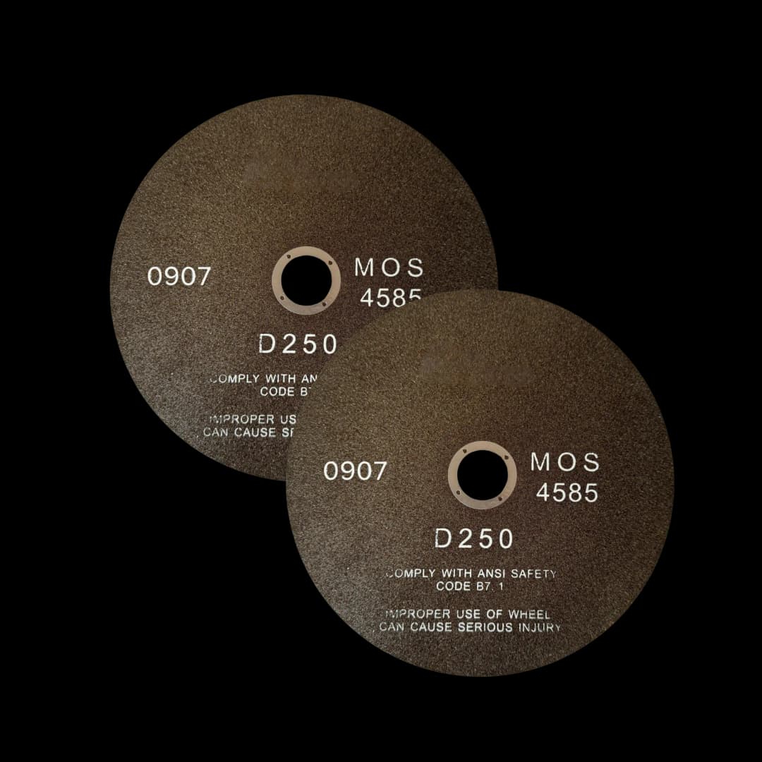
Medium resin-bonded Al₂O₃ blades designed for general ferrous metals including cast iron. For very hard cast irons like ADI, a hard-bond blade for hardened steels may be more appropriate.
- Use a medium resin-bonded Al₂O₃ blade (general ferrous category) for typical cast iron grades, or step up to a hard-bond Al₂O₃ blade (hardened/case-hardened steel category) for very hard cast irons like ADI
- Use a standard abrasive cut-off wheel (0.5-1.0 mm thickness)
- Apply steady, moderate pressure
- Use adequate coolant to prevent overheating
- Allow the wheel to do the cutting - avoid forcing
Note: For very hard cast irons like Austempered Ductile Iron (310 HB), treat the cut like hardened steel: use a hard-bond Al₂O₃ blade, generous coolant flood, and a lighter feed rate. Manage heat with coolant and feed, not by under-speeding the wheel — an under-sped blade glazes and burns instead of cutting.
White iron exception: white cast iron and Ni-Hard / high-Cr grades are very hard (~600 HV) and cut like hardened steel — use a hard-bond abrasive blade (or a CBN wheel where available). Never use a diamond cut-off wheel on white cast iron: at cutting temperatures diamond reacts with iron, dulling the wheel rapidly and leaving a heavily damaged cut surface.
Example Products: Ferrous Abrasive Blades (General & Hardened)Medium resin-bonded Al₂O₃ blades for general cast iron, plus hard-bond Al₂O₃ blades for very hard cast irons like Austempered Ductile Iron (ADI)
For purchasing options and product specifications, see commercial supplier website.
Mounting
Mounting provides edge retention and easier handling. For cast iron, both compression and cold mounting work well. The choice depends on whether edge retention is critical and the hardness of the specific cast iron grade.
Vacuum impregnation for porous castings. Real-world cast iron — especially large gray iron castings with shrinkage porosity, or any sample with visible defects under the as-received surface — needs vacuum (or pressure) impregnation with low-viscosity epoxy before mounting. Impregnation fills the pores and supports surrounding features during polishing; without it, the polishing pad levers material out at pore edges and the artifact looks identical to real solidification porosity (see the Troubleshooting section below for distinguishing the two). After impregnation, finish with a colloidal silica step — it's effectively mandatory after vacuum impregnation to clean up pore-edge pull-out.
Compression Mounting
Compression mounting with phenolic or epoxy resins is suitable for most cast irons. Glass-filled epoxy gives the best edge retention, which can be important for preserving graphite near edges; plain phenolic is acceptable for routine work on softer grades.
- Clean the sample thoroughly to remove cutting fluid and debris
- Place sample in mounting press with appropriate resin
- Apply pressure: 3000-4000 psi for phenolic, 2000-3000 psi for epoxy
- Heat to 150-180°C and hold for 5-8 minutes
- Cool under pressure to room temperature
Cold Mounting
Cold mounting with epoxy resin is also suitable. Liquid epoxy can infiltrate open graphite cavities and surface-connected porosity, supporting the graphite and improving its retention during grinding and polishing — the same mechanism vacuum impregnation exploits.
- Clean the sample thoroughly
- Place sample in mounting mold
- Mix epoxy resin according to manufacturer's instructions
- Pour into mold and allow to cure (typically 4-8 hours at room temperature)
Grinding
Grinding removes sectioning damage and prepares the surface for polishing. For cast iron, use gentle grinding techniques to avoid damaging or removing graphite. The graphite is soft and can be easily pulled out or smeared during grinding.
White iron / Ni-Hard / high-Cr iron exception. The SiC ladder below is for graphite-bearing cast irons (gray, ductile, malleable, ADI, CGI). For white cast iron and Ni-Hard / high-Cr abrasion-resistant grades, switch to a diamond grinding ladder(75 → 30 → 15 → 9 µm on diamond-impregnated discs or films). SiC at ~9.5 Mohs cannot cleanly cut Cr-rich carbides; the abrasive plows them and tears them out, destroying the carbide morphology that's the entire point of metallographic analysis on white iron.
Important: Use lighter pressure than you would for steel. Graphite is soft and can be removed during grinding. Monitor the surface carefully and avoid over-grinding.
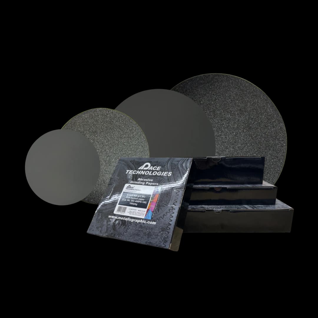
Silicon carbide (SiC) grinding papers in various grit sizes (120, 240, 400, 600) for progressive grinding. Use lighter pressure than for steel to preserve graphite.
Grinding Sequence
- 120 grit: Remove sectioning damage (30-60 seconds per step, lighter pressure)
- 240 grit: Remove previous scratches (1-2 minutes, lighter pressure)
- 400 grit: Further refinement (1-2 minutes, lighter pressure)
- 600 grit: Final grinding step (1-2 minutes, lighter pressure)
Critical Guidelines:
- Use lighter pressure than for steel - graphite is soft and can be removed
- Rotate the sample 90° between each grit to ensure complete removal of previous scratches
- Use water as a lubricant and maintain consistent, light pressure
- Monitor the surface - if graphite starts to pull out, reduce pressure further
- For very hard cast irons like ADI, you can use slightly more pressure, but still be gentle
Polishing
Polishing is critical for cast iron because graphite is revealed by polishing, not etching. The goal is to achieve a mirror-like surface that reveals the graphite structure clearly while preparing the matrix for etching. Use gentle polishing techniques to avoid removing graphite.
Key Principle: Graphite is revealed by proper polishing. Etching reveals the matrix structure (ferrite, pearlite, bainite), but the graphite itself is visible in the polished state. Avoid over-polishing that could remove graphite.
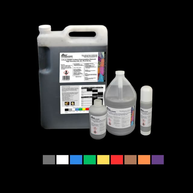
Polycrystalline diamond compound for polishing cast iron. Use gentle pressure to preserve graphite.
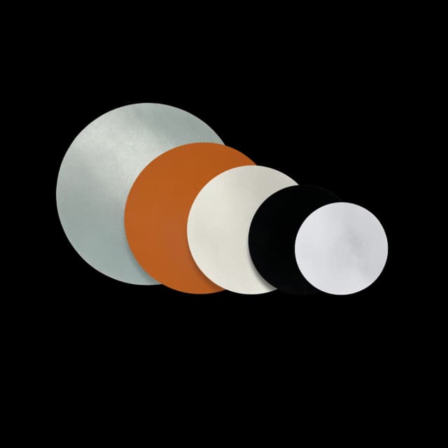
Various polishing pads and cloths. Use lighter pressure and short polishing times for cast iron to preserve graphite — harder pads through 1 µm resist graphite pull-out.
Diamond Polishing
- 9 μm diamond: 3-4 minutes on a hard woven pad — the hard pad supports graphite edges and resists pull-out
- 3 μm diamond: 2-3 minutes on a medium napped cloth, lighter pressure
- 1 μm diamond: 2-3 minutes on a medium napped cloth, lighter pressure
Final Polishing
- 0.05 μm colloidal silica: ~2 minutes on a soft napped or chemotextile pad, very light pressure
- Flush with water for the final 30-60 seconds while still polishing to remove silica residue, then rinse and dry with compressed air
Critical Guidelines:
- Use lighter pressure throughout polishing - graphite is soft and can be removed
- Stay on harder pads and medium napped cloths through 1 µm — long dwell on soft napped cloths plucks graphite out of the matrix and rounds flake edges
- Monitor the surface - graphite should be clearly visible after polishing
- Avoid over-polishing - extended times can remove graphite
- For very hard cast irons like ADI, you can use slightly more pressure, but still be gentle
After polishing, examine the sample under the microscope. The graphite should be clearly visible as dark areas (flakes, nodules, or compacted shapes depending on the cast iron type). If graphite is missing or appears damaged, reduce pressure and shorten the polishing times — do not extend them.
Example Products: Diamond Abrasivessuitable diamond polishing compounds in various particle sizes
For purchasing options and product specifications, see commercial supplier website.
Etching
Etching reveals the matrix structure (ferrite, pearlite, bainite) but does not reveal graphite - graphite is visible in the polished state. The same etchants used for carbon steel work well for cast iron matrices. Nital (nitric acid in ethanol) is the most common etchant.
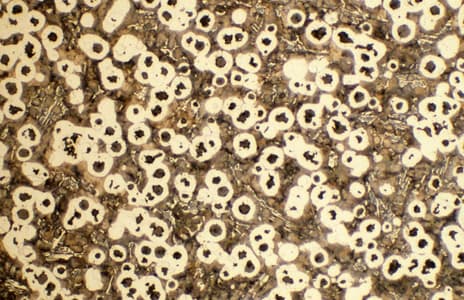
Nodular cast iron after etching, 100X. The matrix structure (ferrite/pearlite) is revealed by etching, while the spheroidal graphite is preserved from polishing.
Common Etchants for Cast Iron
- 2% Nital: General-purpose matrix etch for gray, ductile, malleable, and CGI cast irons. Reveals ferrite grain boundaries and pearlite structure (2 mL HNO₃ in 98 mL ethanol). Swab 5-15 s.
- 4% Picral: Reveals cementite and pearlite cleanly without attacking ferrite boundaries (4 g picric acid in 100 mL ethanol). Swab 10-60 s. Picric safety: store the reagent and any picric acid stock wetted at all times — dry picric acid is a friction- and shock-sensitive explosive. Keep stock bottles topped up; never let them dry out.
- Nital then 4% Picral (sequential etch): The canonical cast-iron matrix workflow when 2% Nital alone leaves pearlite washed out. Apply 2% Nital first (5-15 s swab), rinse, then a second swab of 4% Picral on top — Picral darkens cementite and sharpens the pearlite lamellae against the ferrite background.
- Beraha's I (color tint — first choice for ADI ausferrite): 10 mL HCl + 90 mL H₂O + 1 g K₂S₂O₅ (potassium metabisulfite). Immerse 30-180 s. The handbook etch for ADI because the ausferrite matrix — acicular ferrite + carbon-enriched retained austenite — looks like bainite in grayscale, and Nital cannot reliably separate the ferrite needles from retained austenite (or from any martensite left by short austempering). A color tint etch distinguishes them. Also useful for ferrite/pearlite/bainite color contrast in heat-treated ductile iron.
- 4% Picral or Vilella's (white iron / high-Cr iron): For revealing chromium-carbide morphology in white cast iron, Ni-Hard, and high-Cr abrasion-resistant grades. Vilella's = 1 g picric + 5 mL HCl + 95 mL ethanol; same picric storage rules apply.
Note: a 3-5% Nital bump is sometimes recommended for ADI; treat this as a fallback only. The right answer for ADI ausferrite imaging is a color tint etch, not stronger Nital — Nital cannot separate retained austenite from acicular ferrite (or martensite) no matter how concentrated it gets.
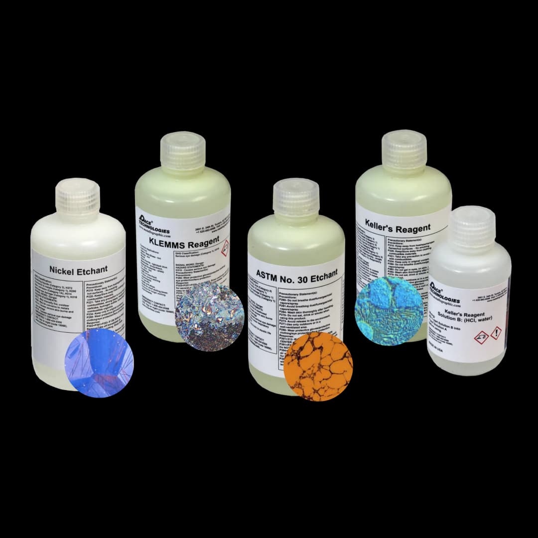
Etching solutions and reagents for cast iron. Common etchants include 2% Nital and 4% Picral. Etching reveals the matrix structure, not the graphite.
Etching Procedure
- Ensure sample is clean and dry after polishing
- Examine the polished surface unetched first — document graphite morphology per ASTM A247 (nodularity rating, graphite type and size charts) before any etching. Etching attacks the matrix and distorts apparent graphite shape, so post-etch nodularity counts on ductile iron are unreliable.
- Select the etchant by family: 2% Nital (or sequential Nital→Picral) for gray/ductile/malleable/CGI matrix; Beraha I for ADI ausferrite; 4% Picral or Vilella's for white-iron carbide morphology
- Apply Nital/Picral/Vilella's by cotton swab; apply Beraha I by immersion
- Etch by time per etchant: 2% Nital 5-15 s; 4% Picral 10-60 s; Vilella's 5-60 s; Beraha I tint 30-180 s
- Immediately rinse with water, then ethanol
- Dry with compressed air
Important Notes:
- Graphite is not revealed by etching — it should already be visible after polishing. Document the unetched view (per ASTM A247 nodularity rating) before etching, since etch attack distorts apparent graphite shape.
- Etching reveals the matrix structure (ferrite, pearlite, bainite, ausferrite)
- Start with shorter etching times (5-10 seconds) and increase if needed
- Default etch for gray, ductile, malleable, CGI: 2% Nital; if pearlite washes out, follow with 4% Picral sequentially
- Default etch for ADI ausferrite: Beraha I tint — not stronger Nital
- Default etch for white iron / Ni-Hard / high-Cr iron: 4% Picral or Vilella's for carbide morphology
Example Products: EtchantsPre-mixed and custom etching solutions for cast iron, including Nital and Picral
For purchasing options and product specifications, see commercial supplier website.
Troubleshooting
Common Issues and Solutions
- Graphite pullout or missing graphite: Too much pressure, over-long polishing, or excessive dwell on soft napped cloths. Reduce pressure, shorten polishing times, keep to harder pads through 1 µm, and monitor the surface carefully. Graphite is soft and easily removed. For porous castings, vacuum-impregnate before mounting.
- Graphite appears smeared: Over-polishing or too aggressive polishing. Reduce polishing time and pressure; the chemo-mechanical colloidal silica step cleans up residual smear.
- Scratches remaining: Insufficient grinding/polishing time or skipped grits. Ensure complete scratch removal at each step, but use lighter pressure.
- Graphite not visible after polishing: May have been removed during preparation. Start over with lighter pressure throughout the process.
- Relief around graphite: Over-polishing or too soft a cloth. Reduce polishing time or use slightly harder cloth, but still maintain light pressure.
- Contamination: Clean between steps, use fresh abrasives, and ensure proper sample cleaning.
- Poor edge retention: Switch to a glass-filled epoxy mount — it wears at a rate closer to the sample than plain phenolic and keeps the sample-mount boundary flat.
- Over-etching: Reduce etching time or use lower Nital concentration. Start with shorter times (5-10 seconds).
- Under-etching: Increase etching time or use higher Nital concentration. Ensure sample is clean before etching.
- Matrix structure not revealed: May need longer etching time or different etchant. Try Picral for pearlitic structures.
Remember: The most common mistake in cast iron preparation is using too much pressure, which removes or damages the graphite. Always err on the side of lighter pressure and gentler techniques.
Explore More Procedures
Browse our comprehensive procedure guides for material-specific preparation methods and get personalized recommendations.