Additive Manufacturing (3D Printing) Sample Preparation
A comprehensive guide to preparing additive manufacturing samples for metallographic analysis, covering unique challenges, sectioning, mounting, grinding, polishing, and etching techniques for revealing build direction, layer interfaces, and process defects.
Table of Contents
Introduction
Additive manufacturing (AM), also known as 3D printing, has revolutionized materials processing and manufacturing. However, the unique characteristics of AM materials, including porosity, layer boundaries, support structures, and anisotropic microstructures, present distinct challenges for metallographic sample preparation. This growing field requires specialized techniques to properly reveal build direction, layer interfaces, and process defects.
AM processes such as powder bed fusion (PBF), directed energy deposition (DED), and binder jetting create materials with microstructures that differ significantly from conventionally processed materials. The layer-by-layer build process results in directional solidification, thermal gradients, and potential defects that must be carefully preserved and revealed during sample preparation.
Key Consideration: Unlike conventional materials, AM samples require careful orientation planning to reveal both the build direction (Z-axis) and layer interfaces (XY plane). Multiple samples may be needed to fully characterize the microstructure.
The core preparation principle: AM alloys follow the preparation recipe of their wrought counterpart. Ti-6Al-4V is prepared like wrought titanium, IN718 like a wrought nickel superalloy, AlSi10Mg like a cast aluminum-silicon alloy, and 316L like wrought austenitic stainless steel. What changes for AM is the attention paid to three things: porosity (vacuum impregnation of open pores before grinding), anisotropy (sectioning and documenting relative to the build direction), and etching for melt-pool boundaries in addition to the conventional microstructural features.
.JPG&w=3840&q=75)
Titanium alloy microstructure showing anisotropic grain structure, similar to what may be observed in AM materials. The directional grain growth and phase distribution are characteristic of layer-by-layer build processes. 400X magnification (DIC).
Unique Challenges with Additive Manufacturing Materials
Porosity
AM materials often contain porosity from incomplete fusion, gas entrapment, or keyhole collapse. These pores can be:
- Lack-of-fusion pores: Irregularly shaped, located between melt tracks and at layer boundaries where adjacent scans failed to overlap fully; they often contain unmelted powder particles
- Gas pores: Small and spherical, typically from gas trapped in the powder or shielding atmosphere
- Keyhole pores: Rounded to near-spherical, usually larger than gas pores and sitting deep in the melt pool, from vapor-cavity (keyhole) collapse under excessive energy input
During preparation, these pores can trap abrasives, polishing compounds, or etchant, leading tocontamination and artifacts. Careful cleaning between steps is essential.
Layer Boundaries
The layer-by-layer build process creates distinct boundaries between layers. These interfaces may contain:
- Oxide films or contamination
- Microstructural differences (grain size, phase distribution)
- Residual stress concentrations
- Potential weak points for failure
Preserving these boundaries during sectioning and preparation is critical for understanding material behavior and process optimization.
Support Structures
Many AM processes require support structures that must be removed post-build. The interface between the part and support material can contain:
- Incomplete fusion zones
- Contamination from support removal processes
- Altered microstructures due to different thermal histories
- Residual stress from support removal
If analyzing support interfaces, careful sectioning to preserve these regions is essential.
Anisotropic Microstructures
The directional solidification and thermal gradients in AM create anisotropic microstructuresthat vary significantly with orientation. Grain growth, phase distribution, and defect density all depend on build direction and location relative to the build plate.
Sectioning Considerations
Sectioning AM samples requires careful planning to reveal the features of interest. The build direction and layer orientation must be considered when selecting the section plane.
Orientation Planning
Plan your sectioning to reveal the features you need to analyze:
- Build direction (Z-axis): Section perpendicular to build layers to reveal layer boundaries, columnar grain growth, and vertical porosity distribution
- Layer plane (XY plane): Section parallel to build layers to reveal in-plane microstructure, grain morphology, and horizontal defect distribution
- Oblique sections: May be useful for revealing three-dimensional relationships
Sectioning Technique
Manage cutting heat through blade selection, flood coolant, and a light feed rate — not by under-speeding the wheel, which glazes the blade — to preserve microstructural features:
- Match the blade class to the alloy being cut: a medium-hard bond Al₂O₃ or CBN blade for nickel superalloys (IN718); a blade rated for hard non-ferrous metals (Ti/Zr) for Ti-6Al-4V; a soft-bond SiC (non-ferrous) blade for AlSi10Mg; a medium-bond Al₂O₃ (general ferrous) blade for 316L, stepping up to a harder-bond Al₂O₃ blade for hardened precipitation-hardening grades like 17-4 PH
- Run abrasive cutoff at standard surface speeds (2,500-4,500 SFM) with a light, steady feed; for small or delicate samples a precision wafering saw at low load gives a much thinner damage layer
- Use thin abrasive blades (0.5-1.0 mm) to minimize kerf loss
- Use adequate coolant to prevent overheating
- For porous materials, use a slower feed rate to avoid tearing
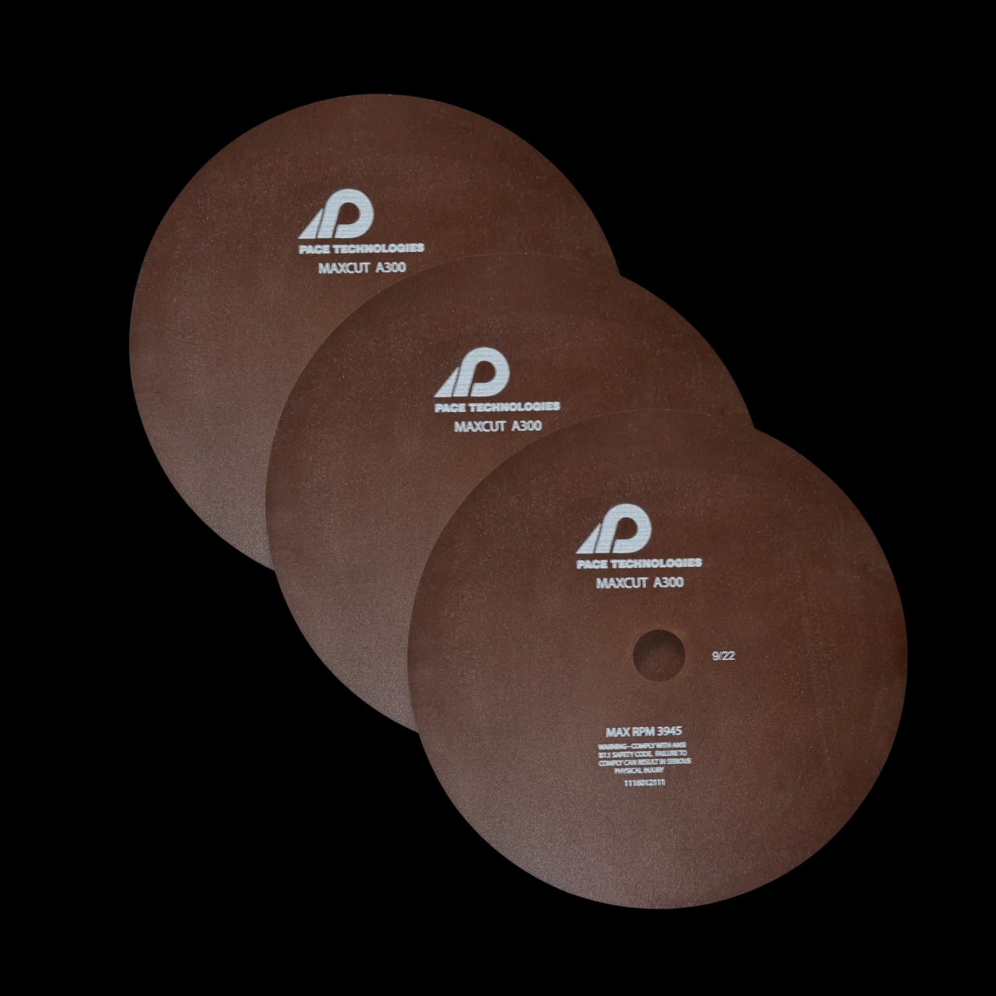
Thin abrasive cut-off blades minimize heat generation and preserve microstructural features in AM materials. Choose the blade class for the alloy being cut: medium-hard Al₂O₃ or CBN for nickel superalloys, hard non-ferrous (Ti/Zr) rated blades for Ti-6Al-4V, soft-bond SiC for aluminum alloys, general ferrous Al₂O₃ blades for 316L, and harder-bond Al₂O₃ for hardened grades like 17-4 PH.
Example Products: Abrasive Cut-Off BladesThin blades for precise sectioning of AM samples with minimal damage
For purchasing options and product specifications, see commercial supplier website.
Mounting Considerations
Mounting AM samples requires special attention to porosity. For samples with open or surface-connected porosity, vacuum impregnation with a low-viscosity epoxy is the right call: unfilled pores trap abrasive during grinding and bleed etchant during etching, while resin-filled pores stay planar and read correctly under the microscope.
Compression Mounting
Compression mounting can work well for AM samples, but consider:
- Standard compression pressures (2,000-4,200 psi) are typically fine; reduce only if a highly porous sample shows pore collapse
- Glass-filled epoxy resins give the best edge retention; plain phenolic is acceptable for routine bulk-structure work
- Compression mounting cannot impregnate open porosity — for porous AM material, prefer castable mounting with vacuum impregnation (below)
- Ensure complete curing to prevent resin shrinkage artifacts
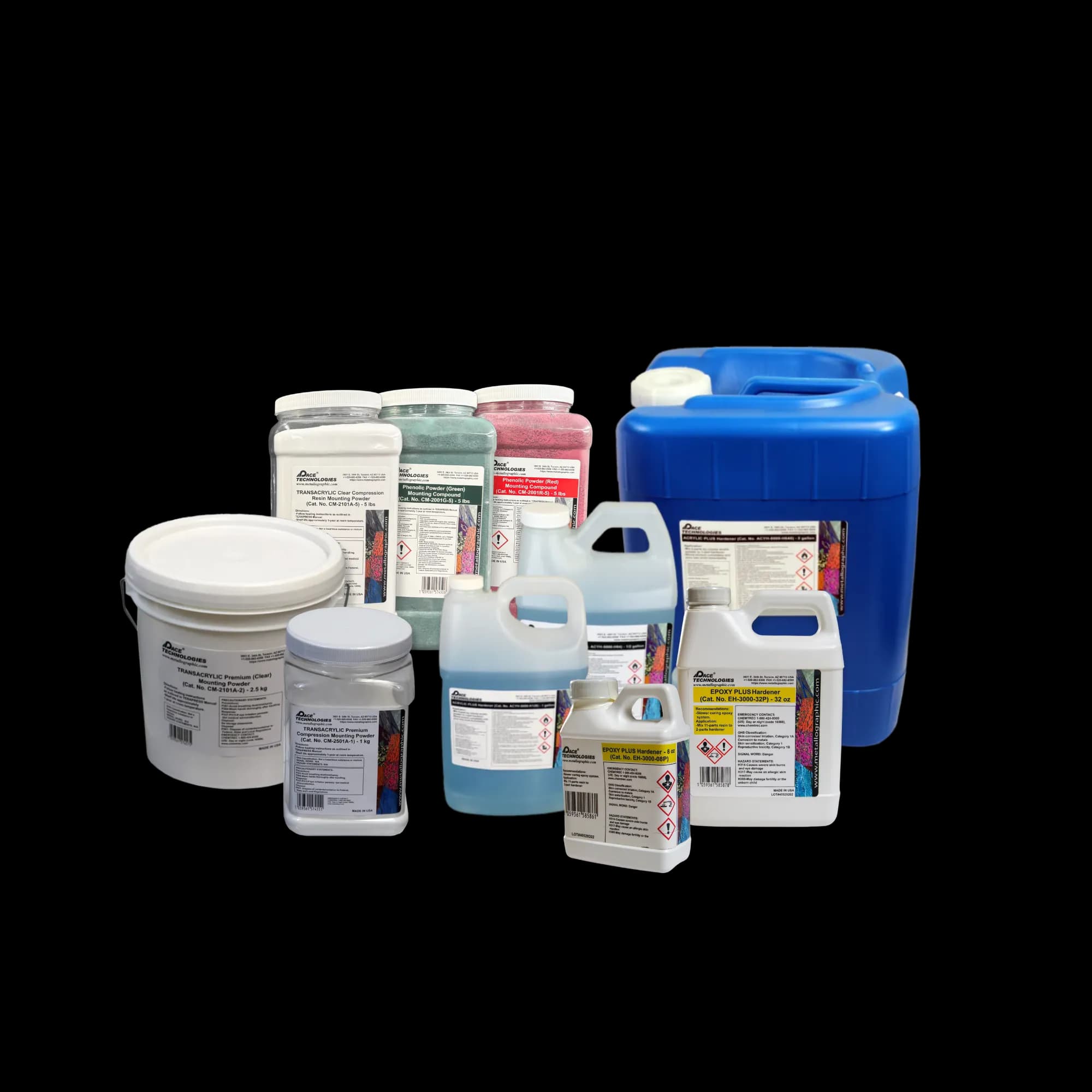
Compression mounting presses for AM samples. Use moderate pressure to avoid collapsing pores in porous materials.
Castable Mounting
Castable mounting may be preferable for highly porous samples:
- Lower pressure reduces risk of pore collapse
- Better penetration into complex geometries
- Use vacuum impregnation for porous materials: draw vacuum (>25 inHg) with the sample in low-viscosity epoxy, then release — optionally following with 1-4 bar of pressure — to drive resin into the pore network
- Longer curing time but better preservation of features
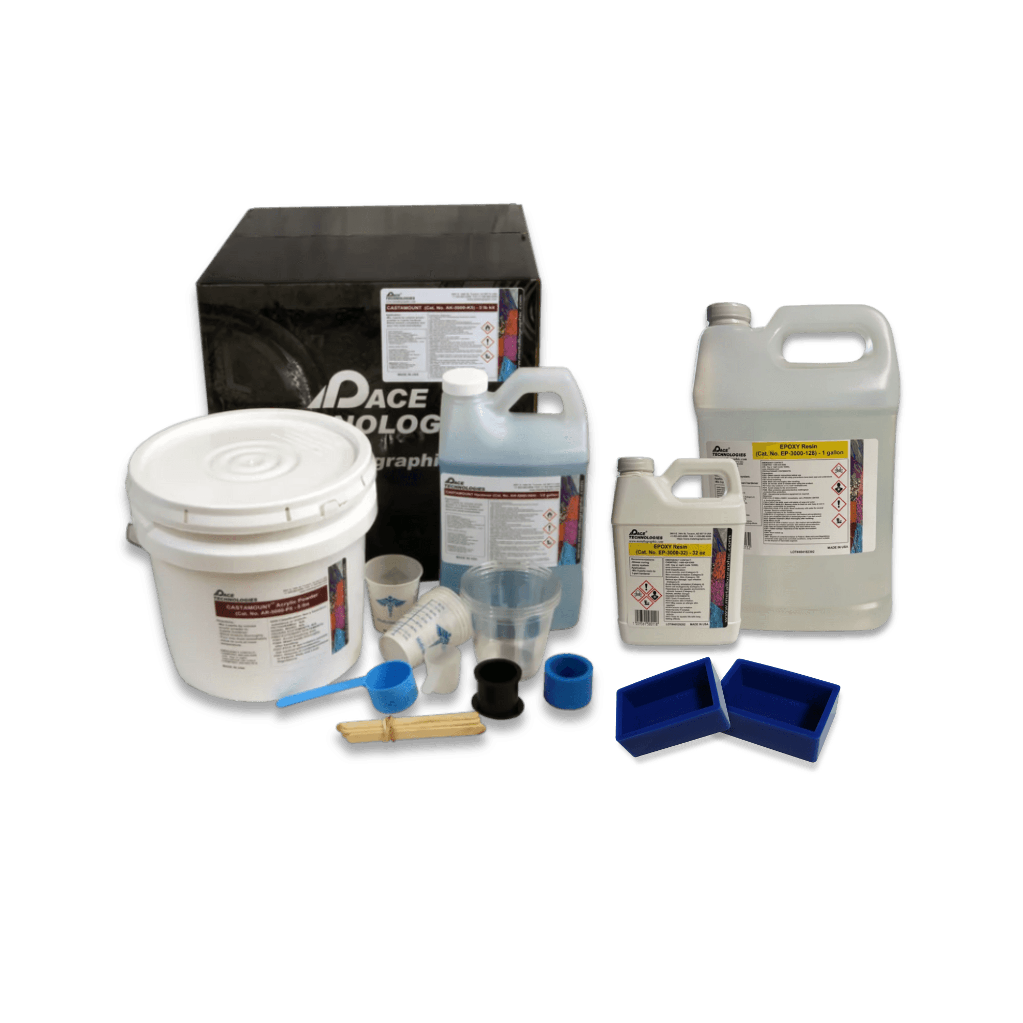
Castable mounting systems with vacuum impregnation capabilities for highly porous AM materials.
Grinding
Grinding AM samples requires careful technique to avoid smearing, pore collapse, and loss of layer boundary definition. The presence of porosity makes these materials more susceptible to damage during grinding.
Grinding Sequence
Use a progressive grinding sequence with careful attention to pressure:
- 120 grit: Remove sectioning damage (30-60 seconds). Use light pressure to avoidsmearing porous regions
- 240 grit: Remove previous scratches (30-60 seconds). Continue with light pressure
- 400 grit: Further refinement (30-60 seconds)
- 600 grit: Final grinding step (30-60 seconds)
Special Considerations
- Light pressure: Use lighter pressure than for dense materials to avoid pore collapse and smearing
- Frequent cleaning: Clean samples thoroughly between grits to remove trapped abrasives from pores
- Rotation: Rotate sample 90° between grits, but be aware of orientation to preserve layer boundary visibility
- Water lubrication: Use adequate water to prevent overheating and remove debris
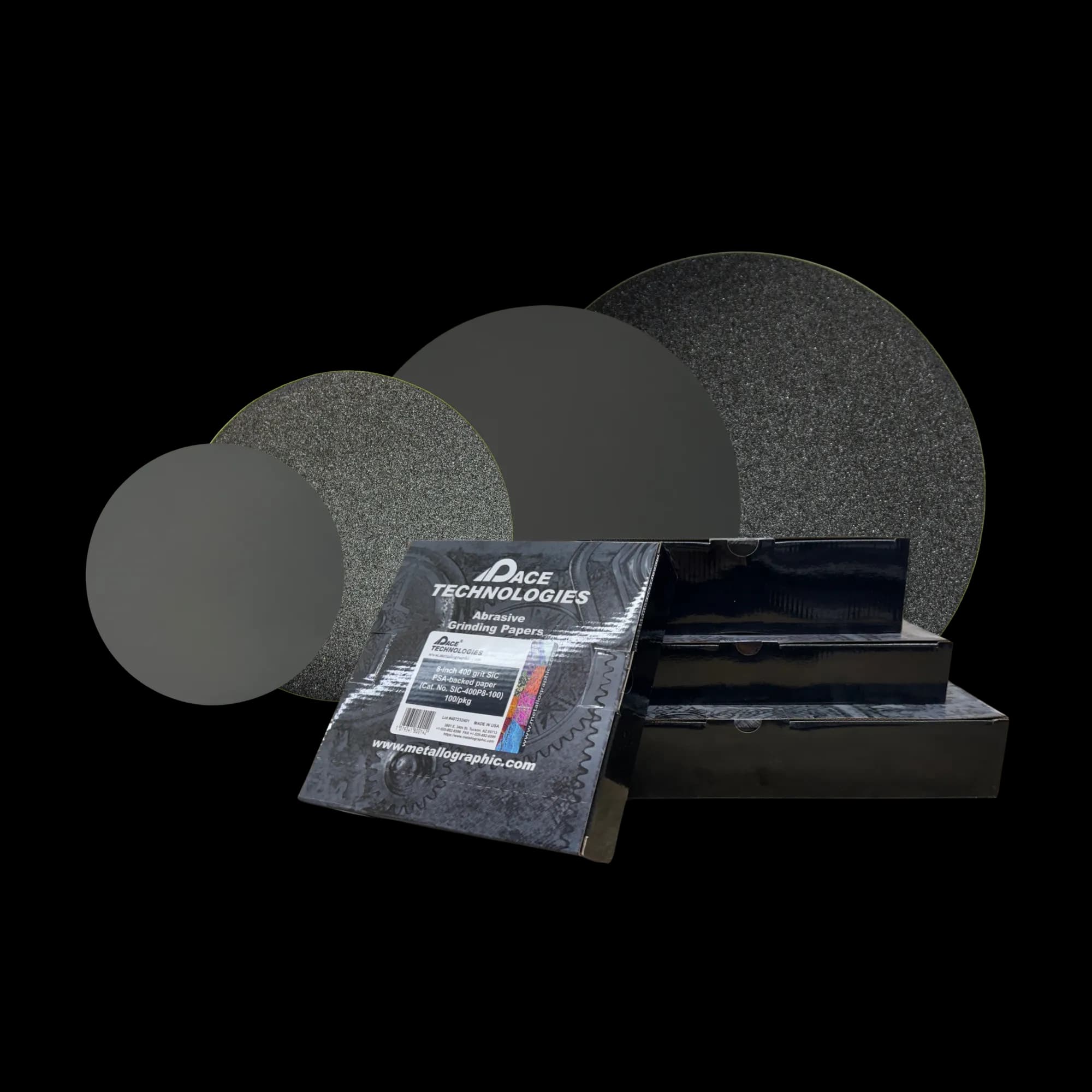
Silicon carbide (SiC) grinding papers in various grit sizes for progressive grinding. Use light pressure to avoid smearing porous regions.
Example Products: Silicon Carbide Grinding Papersappropriate SiC papers for progressive grinding of AM samples
For purchasing options and product specifications, see commercial supplier website.
Polishing
Polishing AM samples requires careful technique to avoid filling pores with polishing compound and to preserve layer boundaries. The anisotropic nature of AM microstructures means that different regions may polish at different rates.
Diamond Polishing
- 9 μm diamond: 3-5 minutes on a hard woven or non-woven pad. Use light pressure
- 3 μm diamond: 3-5 minutes on a medium-hard cloth. Continue with light pressure
- 1 μm diamond: 2-3 minutes on a soft cloth
Follow the polishing recipe for the alloy's wrought counterpart. One AM-specific note: for Ti-6Al-4V, finish with the standard titanium attack polish — colloidal silica with 30% H₂O₂ added (about 1 part H₂O₂ to 5 parts silica) — to remove the stubborn deformation layer titanium retains.
Final Polishing
- 0.05 μm colloidal silica: 1-2 minutes on a soft cloth
- Rinse thoroughly with water, then alcohol
- Use ultrasonic cleaning if available to remove polishing compound from pores
- Dry with compressed air
Special Considerations
- Avoid over-polishing: Can cause relief around pores and layer boundaries
- Frequent cleaning: Clean between polishing steps to prevent compound buildup in pores
- Ultrasonic cleaning: Consider ultrasonic cleaning after final polish to remove trapped polishing compound
- Monitor relief: Check for relief around pores and layer boundaries that may indicate over-polishing
- Vibratory polishing: A vibratory final polish significantly improves AM surface quality over mechanical polishing alone and is generally worth the extra cycle time on AM samples
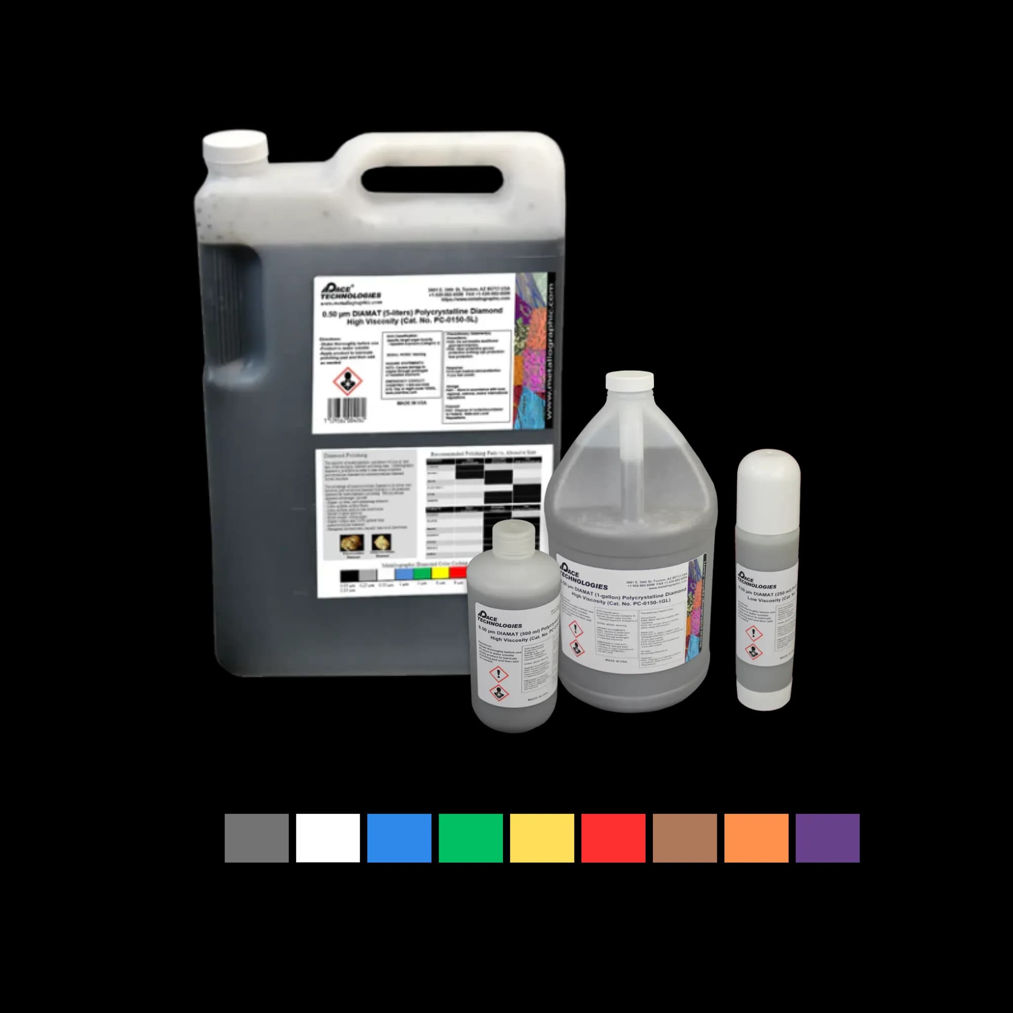
Diamond polishing compounds in various particle sizes for AM materials.
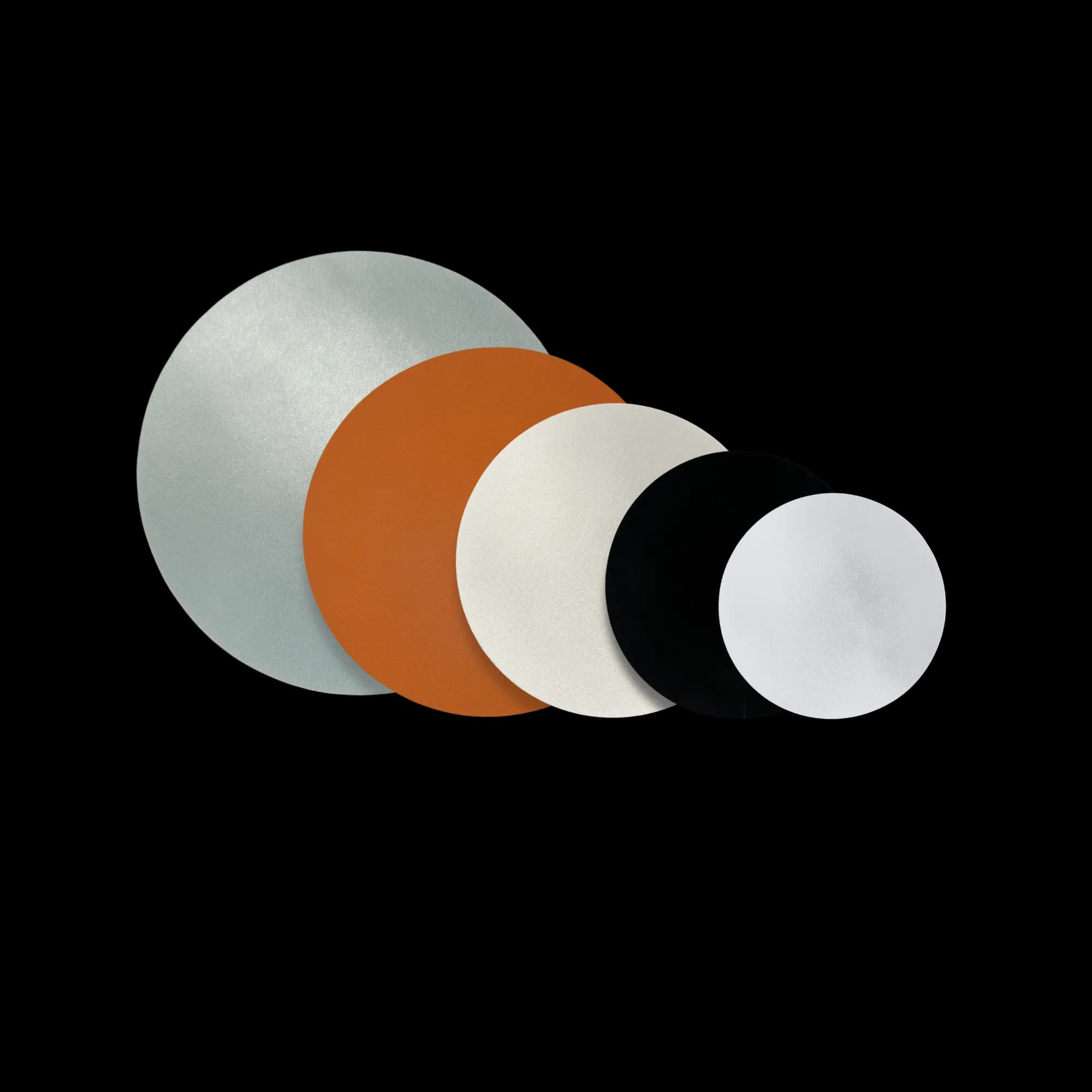
Polishing pads and cloths for different polishing stages. Select appropriate hardness for AM materials.
Etching
Etching AM samples reveals the microstructure, layer boundaries, and process defects. The choice of etchant depends on the base material (stainless steel, titanium, nickel alloys, etc.) and the features you want to reveal.
Etchant Selection
Use standard etchants for the base material, but consider:
- Material-specific etchants: Use the standard etchant for the base alloy: electrolytic 10% oxalic acid or Glyceregia for austenitic stainless steel (316L); Vilella's for martensitic grades and Marble's for precipitation-hardening grades such as 17-4 PH; Kroll's Reagent for titanium (Ti-6Al-4V); Marble's or Modified Kalling's (Kalling's No. 2) for nickel superalloys (IN718); Keller's reagent for aluminum alloys (AlSi10Mg) — Keller's also reveals melt-pool boundaries strongly in AM aluminum
- Electrolytic etching: May provide better control for revealing layer boundaries and fine microstructural features
- Multiple etchants: Different etchants may reveal different features, so consider using multiple etchants on different samples or re-polishing and re-etching
Etching Procedure
- Ensure sample is clean and dry
- Apply etchant with cotton swab or immerse sample
- Etch for appropriate time (may need to adjust from standard times due to microstructural differences)
- Immediately rinse with water, then alcohol
- Dry with compressed air
- Inspect under microscope and re-etch if necessary
Special Considerations
- Layer boundaries: May etch differently than bulk material, creating contrast
- Pores: May trap etchant, requiring thorough rinsing
- Anisotropic response: Different orientations may etch at different rates
- Over-etching: Can obscure fine features, so start with shorter times
- Heat-treated AM material: Stress relief, HIP, or solution treatment erases melt-pool boundaries and the fine cellular solidification structure — expect a more homogenized, conventional-looking microstructure after heat treatment
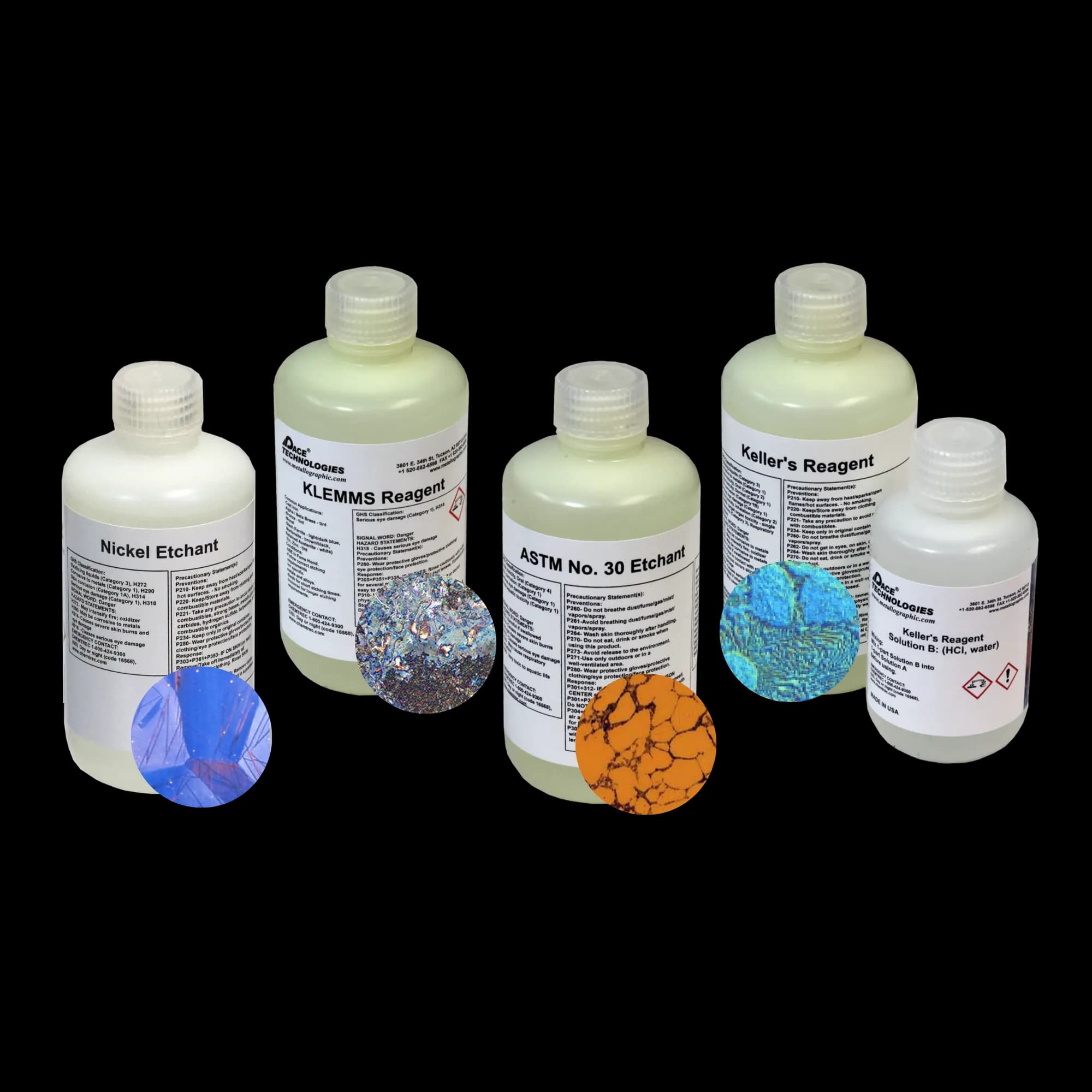
Etching solutions and reagents for AM materials. Use material-specific etchants based on the base alloy (stainless steel, titanium, nickel alloys, etc.).
Example Products: EtchantsEtching solutions and reagents for AM materials
For purchasing options and product specifications, see commercial supplier website.
Revealing Build Direction and Layer Interfaces
One of the most important aspects of AM sample preparation is revealing the build direction and layer interfaces. This requires careful sectioning orientation and appropriate etching.
Sectioning for Build Direction
To reveal build direction (Z-axis):
- Section perpendicular to the build plate (parallel to build direction)
- This reveals layer boundaries, columnar grain growth, and vertical porosity distribution
- Allows analysis of layer-to-layer bonding and fusion quality
Sectioning for Layer Planes
To reveal layer plane microstructure (XY plane):
- Section parallel to the build plate (perpendicular to build direction)
- This reveals in-plane grain morphology and defect distribution
- Shows the microstructure within individual layers
Revealing Layer Boundaries
Layer boundaries may be revealed through:
- Microstructural differences: Different grain sizes or phase distributions at layer boundaries
- Melt-pool boundaries: In powder bed fusion, etching outlines the overlapping melt-pool arcs (the "fish-scale" pattern, especially vivid in AlSi10Mg with Keller's and visible in 316L and IN718) that map directly to the laser scan strategy
- Oxide films: Thin oxide layers that etch differently
- Porosity: Pores concentrated at layer boundaries
- Etching contrast: Different etching response due to microstructural variations
Documentation
Always document the sectioning orientation relative to the build direction:
- Mark the build direction on the sample or mount
- Include orientation information in your notes and images
- Use consistent terminology (e.g., "Z-axis section" or "XY plane section")
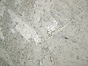
Cast titanium microstructure showing directional solidification patterns similar to those observed in AM materials. The columnar grain growth and layer-like structures demonstrate the importance of proper sectioning orientation to reveal build direction.
Process Defect Analysis
AM processes can introduce various defects that must be preserved and revealed during sample preparation. Understanding these defects is critical for process optimization and quality control.
Common AM Defects
Porosity Defects
- Lack-of-fusion pores: Irregularly shaped, often at layer boundaries, from insufficient energy input or scan overlap; frequently contain unmelted powder particles
- Gas pores: Small and spherical, from trapped gas in powder or atmosphere
- Keyhole pores: Rounded, typically larger than gas pores, from excessive energy input causing vapor-cavity (keyhole) collapse deep in the melt pool
Microstructural Defects
- Incomplete fusion: Lack of bonding between layers
- Grain boundary defects: Abnormal grain growth or boundary migration
- Phase segregation: Non-uniform phase distribution
- Residual stress: May cause microcracking or distortion
Geometric Defects
- Layer misalignment: Shifts between layers
- Surface roughness: From incomplete fusion or support structures
- Dimensional inaccuracy: From thermal distortion or process parameters
Preparation for Defect Analysis
To properly reveal and analyze defects:
- Use careful sectioning to preserve defect locations
- Avoid smearing or filling defects during grinding and polishing
- Use appropriate etchants to reveal defect boundaries
- Consider using multiple sectioning planes to fully characterize defects
- Document defect locations relative to build direction and layer number
Troubleshooting
Common Issues and Solutions
Pores Filled with Polishing Compound
- Problem: Polishing compound trapped in pores
- Solution: Use ultrasonic cleaning after polishing, reduce polishing time, or use less aggressive polishing compounds
Layer Boundaries Not Visible
- Problem: Layer boundaries not revealed after etching
- Solution: Try different etchants, adjust etching time, or check sectioningorientation (may need to section perpendicular to layers). Also confirm the heat-treatment state: HIP or solution treatment erases melt-pool boundaries, and in Ti-6Al-4V they are faint even as-built because the β→α transformation overwrites them — look for columnar prior-β grains instead
Smearing in Porous Regions
- Problem: Material smeared over pores during grinding or polishing
- Solution: Reduce pressure, use sharper abrasives, or increase cleaning frequency
Relief Around Pores
- Problem: Excessive relief making pores appear larger than they are
- Solution: Reduce polishing time, use harder polishing cloths, or adjust polishing pressure
Poor Edge Retention
- Problem: Porous edges rounding or losing definition
- Solution: Use harder mounting materials, reduce polishing time at edges, or use edge retention techniques
Anisotropic Polishing
- Problem: Different regions polishing at different rates
- Solution: This is normal for AM materials; adjust polishing time to ensure all regions are properly polished, or use longer polishing times
Explore More Procedures
Browse our comprehensive procedure guides for material-specific preparation methods and get personalized recommendations.